
Enter the required information into the electrical wire gauge calculator and find out the correct wire size.
About Electrical Wire Gauge Calculator
The Electrical Wire Gauge Calculator tells you how can determine the minimum ‘American Wire Gauge’ (AWG) size for a conductor capable of carrying your required load over a specific distance without excessive voltage drop. To do this, you need to input details such as the supply voltage and phase, continuous current, one-way wire length, conductor material, and the maximum voltage drop you are willing to accept. The calculator will then display a recommended minimum wire size along with the underlying calculations.
It works for 12V and 24V DC systems (solar, RV, marine, off-grid, automotive, LED lighting), for 120V and 240V AC branch circuits and feeders, and for three-phase supplies. Before you start, gather four things: the operating voltage, the load current in amps, the distance from the source to the load, and whether the wire is copper or aluminum.
How to Use the Wire Gauge Calculator
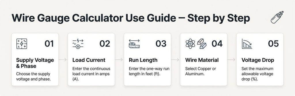
- Choose the supply voltage and phase. Pick the voltage the circuit actually operates at, such as 12, 24, 120, 240, or 480, and whether it is DC, single-phase AC, or three-phase AC. The phase matters because it changes how much conductor length the current travels through. For a 240V circuit feeding a well pump, air compressor, or EV charger, that is normally single-phase 240V. A common mistake is entering 120V for a 240V appliance, which makes the allowable drop in volts far too small and pushes the result toward oversized wire.
- Enter the continuous load current. Use amps. Take the number from the nameplate of the equipment, the fuse or breaker rating for a loop of fixed loads, or a sum of your loads divided by voltage (watts ÷ volts = amps). “Continuous” means the load runs three hours or more, and the NEC treats such loads more strictly than short-duration ones. If you only know watts, do the division at the actual circuit voltage. A 1,200 W inverter draws about 100 A at 12V and only about 10 A at 120V.
- Enter the one-way run length in feet. Measure from the source (panel, battery, combiner box) to the load along the path the wire will take, not in a straight line. Enter one direction only. The calculator accounts for the return path itself, so entering the round-trip distance double-counts and oversizes the wire.
- Select copper or aluminum. Aluminum has about 64% higher resistance than copper for the same gauge, so it needs a larger size for the same result. Also, aluminum in a given AWG size has lower ampacity than copper, and it requires terminals rated for it.
- Set the maximum allowable voltage drop. This is a percentage of the supply voltage. Many designers aim for 3% on a branch circuit, and the NEC suggests (in informational notes, not as a mandatory rule) keeping the total from the source to the farthest outlet at or under 5%. Sensitive DC equipment, such as electronics, LED drivers, and battery chargers, is often held to a tighter figure like 2%.
What the Results Mean
Recommended Minimum Wire Size. The smallest AWG or kcmil size whose resistance keeps the drop within your target. Smaller AWG numbers are thicker wire, so 6 AWG is heavier than 10 AWG. Anything larger than the recommendation also works electrically; anything smaller does not.
Actual Provided CM. The circular mil area of the recommended wire. Circular mils measure conductor cross-section, and it is the size the calculator compares against the minimum area it computed. Because wire only comes in standard sizes, this number is nearly always larger than the minimum theoretical requirement.
Calculated Voltage Drop. The volts (and percentage) actually lost over your run with the recommended wire. It is always at or below your target.
Max Drop Target Allowed. Your percentage limit converted to volts, for example 3% of 240V = 7.2V. This is the ceiling the wire is being sized against.
Load Voltage at the End of the Run. Supply voltage minus the calculated drop. This is what the equipment at the far end actually receives.
NEC Ampacity Rating. The current the conductor is allowed to carry under the NEC ampacity tables, which is a separate question from voltage drop. A wire can pass the drop test and still be too small to carry the current safely, and the reverse is common on long runs. The final wire has to satisfy both, so the calculator reports the ampacity next to the drop result.
The Formula Behind the Result
The calculator sizes wire from the area that the allowed voltage drop demands: CM = (K × I × L × M) ÷ VD
Where:
- CM = minimum conductor area in circular mils
- K = resistivity constant, in ohm-circular mils per foot. Commonly 12.9 for copper and 21.2 for aluminum, which are values near 75°C conductor temperature
- I = load current in amps
- L = one-way length in feet
- M = phase multiplier: 2 for DC and single-phase AC (current goes out and comes back), or 1.732 for three-phase
- VD = allowable voltage drop in volts, which is supply voltage × the drop percentage
The calculator then selects the next standard AWG size with a circular mil area at or above this figure. To check the drop for the wire it chose, the same equation is rearranged: VD = (K × I × L × M) ÷ CM(actual), and the percentage drop is VD ÷ supply voltage.
This is a resistance-based calculation. It fits DC circuits and typical AC building wiring very well. For very large conductors on long AC runs, reactance and skin effect add a bit more drop that this method does not model, so a detailed AC analysis is appropriate for heavy feeders.
Worked Example: 240V Single-Phase Feeder
240V single-phase load draws 40 A continuously. The run is 100 ft one way, in copper, with a 3% drop limit.
- Allowed drop: 240 × 0.03 = 7.2 V
- Minimum area: CM = (12.9 × 40 × 100 × 2) ÷ 7.2 = 103,200 ÷ 7.2 ≈ 14,333 CM
- Choose the size: 10 AWG is 10,380 CM, which is too small. 8 AWG is 16,510 CM, which meets the requirement. The recommendation is 8 AWG.
- Actual drop with 8 AWG: (12.9 × 40 × 100 × 2) ÷ 16,510 = 103,200 ÷ 16,510 ≈ 6.25 V, which is about 2.60%.
- Load voltage: 240 − 6.25 ≈ 233.75 V
- Ampacity: 8 AWG copper is listed at 50 A in the 75°C column of the NEC table. A 40 A continuous load times 125% is 50 A, so it lands right at the limit. There is no margin, which is worth noticing. The drop calculation alone would have hidden that.
12V DC Example
A 20 A load sits 15 ft from a 12V battery, in copper, with a 3% limit. Allowed drop = 12 × 0.03 = 0.36 V. CM = (12.9 × 20 × 15 × 2) ÷ 0.36 = 7,740 ÷ 0.36 = 21,500 CM. 8 AWG (16,510) is too small, so 6 AWG (26,240 CM) is chosen. Actual drop = 7,740 ÷ 26,240 ≈ 0.295 V (2.46%), leaving about 11.71 V at the load. Ampacity for 6 AWG copper is 65 A.
Percentage Drop vs. Volts Lost
A percentage sounds the same at every voltage, but it is not the same amount of trouble. Take a 20 A load, 20 ft one way, copper, 3% limit:
- At 12V, the allowed drop is 0.36 V. The required area is (12.9 × 20 × 20 × 2) ÷ 0.36 ≈ 28,667 CM, so 4 AWG (41,740 CM).
- At 24V, the allowed drop is 0.72 V. The required area is about 14,333 CM, so 8 AWG (16,510 CM).
Same current, same distance, same percentage, and two wire sizes different. The lower the voltage, the smaller the number of volts you can afford to lose. That is why 12V wiring gets thick so quickly, and why a 24V system that delivers the same power at half the current is much easier to wire. Keep in mind this comparison holds current constant, which is the calculator’s premise.
Situations Where the Calculator Helps
- Wiring a subpanel, garage, workshop, or outbuilding at a distance from the main panel, where a 240V feeder could be long enough to make the ampacity-only size inadequate.
- Running a well pump, EV charger, or air compressor, where undervoltage at the motor causes stress and nuisance trips.
- Sizing 12V or 24V wiring in an RV, boat, van conversion, or off-grid solar system, where a 3% drop is a fraction of a volt.
- Checking whether an existing run of wire is adequate before adding a load.
- Comparing copper and aluminum for a long feeder, since aluminum costs less per foot but needs a bigger gauge.
Common Mistakes
- Entering the round-trip length. The tool wants one way only.
- Using the breaker rating as the load. A 30 A breaker on a 12 A load sizes for 30 A. Use the actual continuous load if you know it, and let the breaker and wire be sized in the proper order.
- Sizing at the wrong voltage. A 240V appliance entered as 120V changes the allowable drop and the current.
- Checking only voltage drop. The calculated drop being fine does not mean the wire is legal for the current; read the ampacity output too.
- Forgetting the derating. Ambient heat, several current-carrying conductors bundled in one conduit, and long runs at high current all reduce ampacity. The Conduit Fill Calculator helps with the physical side of that.
- Assuming a bigger gauge number means bigger wire. In AWG, it is the reverse.
Accuracy, Assumptions, and Limitations
The result is an engineering estimate for planning and checking, not a substitute for a permit set or a licensed electrician’s judgment. The K values assume a conductor temperature of about 75°C. A cooler wire has slightly lower resistance and a hotter one has more, so a wire running near its ampacity limit in a hot attic will drop somewhat more than calculated. Solid and stranded conductors of the same gauge differ a little in resistance, and the calculation treats them alike.
The method uses resistance only. It ignores reactance, harmonics, and power factor. It also assumes a steady load: motor startup current can be several times the running current and creates a brief, much deeper voltage sag that this calculation does not show.
The ampacity output reflects NEC table values for the given conductor. Terminal temperature ratings, overcurrent protection limits (such as the limits for 14, 12, and 10 AWG copper), and local amendments can restrict what you may actually install.
Practical Tips
- If the load will grow, such as adding an EV charger or a second heater later, size the wire for the future current. Pulling new wire costs far more than the price difference between two gauges.
- Measure wire length along the actual route, including vertical runs and the extra length needed to reach the panel and the load. Adding 10% to a tape-measured distance is often more realistic.
- For 12V and 24V systems, tighten the drop target to 2% when the load is a charger, electronics, or a motor. The margin costs little and prevents undervoltage faults that are hard to diagnose.
- When the calculator lands just under a limit, as in the 40 A example, check both the drop and the ampacity, and consider stepping up a size for headroom.
Reference Table: Common Copper AWG Sizes
| AWG | Area (circular mils) | Ampacity, 75°C copper (NEC Table 310.16) |
| 14 | 4,110 | 20A |
| 12 | 6,530 | 25 A |
| 10 | 10,380 | 35 A |
| 8 | 16,510 | 50 A |
| 6 | 26,240 | 65 A |
| 3/0 | 167,800 | 200 A |
| 4/0 | 211,600 | 230 A |
These are conductor ampacities, not breaker sizes. Small-conductor overcurrent limits (15 A for 14 AWG, 20 A for 12 AWG, 30 A for 10 AWG) still apply to typical circuits. For Actual standard you can check ASTM B258, the standard for AWG conductor dimensions.
Frequently Asked Questions
What wire gauge do I need for a 12V run?
It depends on current and distance more than on the voltage itself. A 20 A load 15 ft away needs 6 AWG at a 3% drop, and a 20 A load 20 ft away needs 4 AWG. Enter your own current and length to get your number.
Does the calculator work for DC and AC?
Yes. DC and single-phase AC use the same two-conductor method, and three-phase uses a different multiplier, which is why the tool asks for the phase.
Why is the recommendation thicker than what the ampacity table suggests?
Because the drop requirement, not the current-carrying limit, is the controlling factor for long runs. The recommended size is the larger of what the two checks would demand.
How long can a 240V circuit be before drop becomes a problem?
There is no single length. It scales with the current, the wire gauge, and your percentage limit. Run the numbers with your actual load; a 40 A load on 8 AWG copper reaches about 2.6% at 100 ft, for example.
Is 3% required by code?
No. The NEC recommends 3% for branch circuits and 5% overall in informational notes, but these are guidelines rather than enforceable requirements, and other standards for specific equipment, such as motors or fire alarm systems, may set their own limits.
Related Tools
To analyze a specific existing wire rather than pick a new one, use the AC & DC Voltage Drop Calculator, which takes a chosen gauge and reports the drop directly. Once you know your wire size, the Electrical Conduit Fill Calculator shows how many conductors of that size fit in a given conduit. More Calculators