
This voltage drop calculator tells you how much voltage a wire or cable loses between the power source and the load. Enter the required input and get returns the voltage drop.
It works for DC systems (solar arrays, battery banks, 12V and 24V wiring) and for AC circuits (branch circuits, feeders, and long runs to outbuildings, pumps and EV chargers). It is most useful when a run is long, the current is high, or the voltage is low. Before you start, have these five things ready: the system voltage, whether the wire is copper or aluminum, the wire size, the one-way length of the run, and the current the load will draw.
Want to see how the result is worked out? Read our guide to the voltage drop formula for AC and DC circuits, with step-by-step examples.
How to Use the AC & DC Voltage Drop Calculator
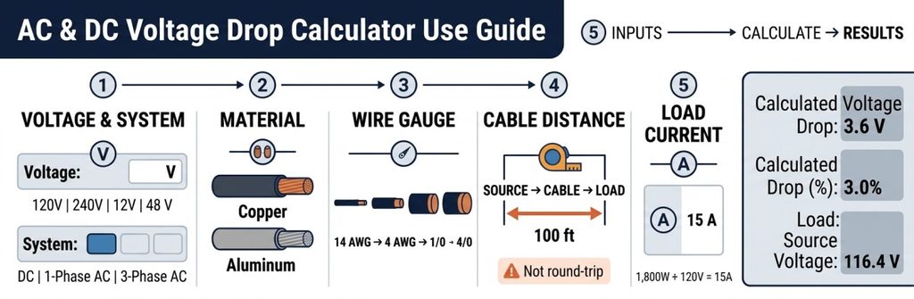
- Circuit voltage and system. Enter the nominal source voltage (120 V, 240 V, 12 V, 48 V and so on) and pick the system type: DC, single-phase AC or three-phase AC. Use the voltage measured at the source, not the load. The system type matters because it changes how many conductors carry current. A common mistake is entering 120 V for a circuit that is really 240 V line-to-line, which makes the percentage look twice as bad as it is.
- Conductor material. Choose copper or aluminum. Aluminum has higher resistance for the same size, so the same gauge loses noticeably more voltage. Check the cable jacket or the panel schedule if you are not sure which you have. Aluminum feeders are easy to mistake for copper once they are installed.
- Wire gauge. Select the size in AWG or kcmil. The number runs backwards: 14 AWG is thin and 4 AWG is thick. Wire in the 1/0 to 4/0 range is still AWG, and anything above 4/0 is measured in kcmil. The size is printed along the insulation. If you are comparing options, run the same circuit with two or three sizes.
- One-way circuit distance. Enter the distance from the source to the load in feet, measured along the actual cable path, not in a straight line. Enter one-way length only. The calculator accounts for the return path itself. Entering the round-trip length is the most common error, and it doubles the result.
- Load current. Enter the current in amperes. For a fixed appliance, use the nameplate amps. For a motor, use the running current, not the starting current. If you only know watts, divide by voltage (a 1,800 W heater on 120 V draws 15 A). For continuous loads, use the current the load will actually carry, not the breaker rating, unless you are deliberately sizing for the worst case.
What the Results Mean
Voltage drop is the voltage lost in the conductors, in volts and as a percentage of the source voltage. This is the headline number. A 4 V drop on a 120 V circuit is 3.3%, but the same 4 V on a 12 V circuit is 33%, which is why the percentage matters more than the raw volts.
Voltage at load terminal is what remains for the equipment after the wire takes its share. Motors, LED drivers, pumps and electronics all have a minimum voltage below which they run hot, run poorly or shut off.
NEC compliance status compares the drop with the National Electrical Code’s recommended maximums: 3% on a branch circuit or feeder, and 5% for the feeder and branch circuit combined. These appear as informational notes in the NEC (for example in 210.19 and 215.2).
They are recommendations, not enforceable requirements for ordinary circuits, although they become mandatory in some specific cases, such as certain fire pump and emergency systems, and your local jurisdiction or project specification may adopt them as a rule. Treat the status as a design check and confirm with your inspector when it matters. you can read the National Electrical Code for free on NFPA’s site.
Conductor power loss is the power turned into heat inside the wire, in watts. It is energy you pay for and never use, and it is also heat the cable and its surroundings must shed.
Total resistance (loop) is the resistance of the full round trip, out on one conductor and back on the other, in ohms. The voltage drop is this figure multiplied by the current.
Conductor cross-section is the cross-sectional area of the selected wire, in circular mils (or mm²). A bigger cross-section means lower resistance and less drop.
Ampacity limit (75°C) is the maximum continuous current the wire can carry using the 75°C column of NEC Table 310.16, which is the usual termination rating for most breakers and lugs. This is a separate question from voltage drop. A wire can pass one check and fail the other, so look at both numbers.
The Voltage Drop Formula
For a single-phase AC or DC circuit: VD = 2 × K × I × L ÷ CM
For a three-phase circuit, replace the 2 with √3 (about 1.732): VD = 1.732 × K × I × L ÷ CM
Where:
- VD = voltage drop, in volts
- K = resistivity of the conductor in ohm-circular mils per foot. About 12.9 for copper and 21.2 for aluminum at 75°C
- I = load current, in amperes
- L = one-way length of the run, in feet
- CM = conductor cross-section in circular mils (for example, 6,530 for 12 AWG)
The percentage drop is then: % drop = VD ÷ source voltage × 100
You can also work from the resistance per 1,000 ft published in tables such as NEC Chapter 9, Table 8: VD = 2 × I × R × L ÷ 1,000, where R is in ohms per 1,000 ft. Both methods give nearly the same answer. Small differences of a few percent come from the temperature and stranding assumptions behind the resistance value.
This is a resistance-only calculation. It is accurate for DC and for AC on small and medium conductors. On large AC conductors (roughly 1/0 and up), reactance starts to add to the drop, and at low power factor the real drop can be higher than a resistance-only figure suggests. If you are sizing large feeders, an impedance-based calculation is more appropriate.
Worked Example
A 120 V, single-phase circuit feeds a workshop 75 ft away (one-way). The load is 16 A. The cable is 12 AWG copper.
Inputs: V = 120, K = 12.9, I = 16 A, L = 75 ft, CM = 6,530
Calculation:
- VD = 2 × 12.9 × 16 × 75 ÷ 6,530
- VD = 30,960 ÷ 6,530
- VD ≈ 4.74 V
Percentage drop = 4.74 ÷ 120 × 100 ≈ 3.95%
Voltage at the load = 120 − 4.74 = 115.26 V
Loop resistance = 4.74 ÷ 16 ≈ 0.296 Ω
Power loss = 16 × 4.74 ≈ 76 W (the same as I²R: 16² × 0.296)
What it means: The wire is well within its ampacity (12 AWG copper is rated 25 A in the 75°C column), but the drop is about 3.95%, over the recommended 3%. The workshop gets about 115 V, and roughly 76 W is wasted as heat in the cable. A sag like this is often what makes lights dim or a motor struggle when it starts.
Trying a larger wire: Stepping up to 10 AWG copper (10,380 CM) gives 30,960 ÷ 10,380 ≈ 2.98 V, or about 2.49%, which is under 3%. The larger wire fixes the problem without changing anything else in the circuit.
Common Situations Where the Calculator Helps
- Long runs to outbuildings, wells, barns or detached garages, where a wire that is fine for the amperage is too thin for the distance.
- Low-voltage DC systems such as solar, RVs, boats and battery banks. At 12 V or 24 V, even a short run can lose a large percentage.
- EV charger, welder and pump circuits, which draw high current for long periods.
- Checking an existing install when lights dim, a motor runs hot, or a device resets under load.
- Comparing copper and aluminum, or checking whether a bigger wire size pays for itself.
- Planning a project before you buy wire, since running the numbers first is cheaper than pulling a larger cable later.
Voltage Drop vs. Ampacity
These two checks answer different questions. Ampacity is about heat: how much current the insulation can take without overheating. Voltage drop is about performance: how much voltage the load still has once the current has passed through the wire. Short, heavily loaded runs tend to be limited by ampacity. Long runs, especially at low voltage, are usually limited by voltage drop. The wire must satisfy both, so the correct size is the larger of the two results.
Accuracy, Assumptions, and Limitations
The result is a design estimate, not a measurement of a real installation.
- It assumes the current is steady and equal to the value you enter. Real loads vary.
- It uses a fixed conductor resistance, generally the value at 75°C. Actual resistance rises as wire heats up and falls when it’s cool, so the real drop varies with temperature and loading.
- It assumes a single load at the end of the run. A circuit with several outlets or loads spread along it drops less than this worst case.
- It is resistance-based. Reactance and power factor, which matter for large AC conductors, are not included.
- Resistance values differ slightly between sources such as NEC Table 8, wire manufacturers (Southwire and others publish their own tables) and different assumptions about stranding. Expect answers within a few percent of each other, not identical numbers.
- Connections, terminals and splices add small resistances that are not modelled.
- The NEC 3%/5% figures are recommendations for most circuits, and local codes and project specifications may differ.
For anything safety-critical, or for work that will be inspected, confirm with a licensed electrician or your local authority.
Practical Tips
- Solve for the drop, then size up. If the result is a little over 3%, try one wire size larger. The change in drop between sizes can be substantial.
- Run the calculation at the full load. For a circuit that will be loaded near its rating, use the maximum current, since that is when the drop is worst.
- Measure the run after routing is decided, not from the plan view, since going up walls and around obstacles adds length.
- On DC systems, aim lower than 3%. Many low-voltage designs target 1–2%, because a small absolute loss at 12 V is a large fraction of the supply.
- Check the voltage at the load if you already have the circuit. A meter reading with the load running, compared with the reading at the source, gives you the true drop to compare with the voltage drop calculator.
Reference Table
Approximate maximum one-way distance (in feet) to stay within a 3% drop on a 120 V single-phase circuit, using copper conductors (K = 12.9):
| Wire size | 10 A | 15 A | 20 A |
| 12 AWG | 91 ft | 61 ft | 46 ft |
| 10 AWG | 145 ft | 97 ft | 72 ft |
| 8 AWG | 230 ft | 154 ft | 115 ft |
These are a quick check only. For 240 V circuits the allowed distance roughly doubles at the same current, and aluminum reduces it by about 40%. Also note that other code rules apply to small wire sizes: 12 AWG copper is generally limited to a 20 A breaker, regardless of what its ampacity would permit.
Frequently Asked Questions
What is an acceptable voltage drop?
The NEC recommends no more than 3% on a branch circuit or feeder, and no more than 5% for the total from the service to the load. Some equipment has tighter limits, so check the manufacturer’s specification.
Is the NEC voltage drop limit mandatory?
For most ordinary circuits it is an informational note, not a requirement. It is enforceable in certain cases, such as some fire pump and emergency systems, or where your local code or project specification requires it. Even where it isn’t required, it is good practice.
Does the calculator work for DC?
Yes. DC uses the same single-phase formula, since current goes out and comes back on two conductors. Select the DC system type and enter the DC voltage.
Why does the calculator use one-way distance?
Because it’s easier to measure and the formula already includes the return path. Entering the round-trip length would double the drop.
How do I reduce voltage drop?
Use a larger wire, shorten the run, use a higher circuit voltage, or reduce the current. Increasing the voltage from 120 V to 240 V for the same power halves the current and cuts the percentage drop by a factor of four for the same wire.
Related Tools
If you know the load and need to choose a conductor size, start with the Electrical Wire Gauge Calculator, then come back here to check the drop over your actual distance. Once the conductor size is settled and you are running several wires through a raceway, the Electrical Conduit Fill Calculator shows whether they’ll fit. More Calculators